EQ-001 — Main DC panel (DCP)
← Equipment Register · Browse equipment
Survey status: Installed, photographed and owner-identified; electrical configuration unverified. The owner confirms this is Ragtime’s original Moody 336 panel. The photograph establishes the visible front layout, not the internal wiring or condition.
Identity and location
| Field | Value |
|---|---|
| Permanent equipment ID | EQ-001 |
| Equipment | Main DC panel (DCP) |
| Register category | DC distribution and controls |
| Equipment class | EQ |
| Reported location | Chart table |
| Inventory state | Installed; front photographed; circuits and ratings unverified |
| Manufacturer / model | Original Moody 336 distribution panel (owner-confirmed); actual component manufacturer and part number unknown |
| Serial / part number | Not recorded |
| Last onboard verification | 31 October 2026: owner identification and front photograph only; no physical circuit inspection |
Original reference and notes: Parent panel assembly. Individual circuit breakers retain separate equipment IDs. The owner identifies the complete faceplate as original Moody 336 equipment.
Photographic evidence
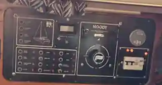
Owner-supplied photograph, 31 October 2026, cropped/optimised for this page. Photograph is visual evidence only, not an as-built wiring inspection.
Visible layout
- Lower left: twelve circular control/breaker positions in a three-column, four-row grid, with adjacent red indicators and engraved function labels. The 31 October 2026 close-up confirms the bottom-right position
3,4is marked “VHF AIS”; the owner identifies this as the 10 A breaker CB-003; the owner confirms it directly supplies the COM-frame fuse board; wiring not independently tested. All other uninvestigated ratings and circuit mappings remain open. - Upper left: EQ-002 comprises the original Moody NAV LTS panel with four vertically stacked 10 A circuit breakers and an illuminated yacht outline. Owner-confirmed breaker functions from top: masthead (CB-001), steaming (CB-002), deck (CB-004), navigation bow/stern (CB-005). The yacht-outline indication wiring is not independently traced. NAV lighting overview.
- Upper middle: a rectangular meter or display and adjacent small control(s); exact functions unconfirmed.
- Centre right: a prominent MOODY-branded module containing a rotary selector. It resembles a multi-position battery selector, but the function and terminal arrangement must be confirmed.
- Far right: a round display/instrument and a white breaker or RCD-type device mounted on a black section. Exact electrical type, ratings and retrofit status unknown.
Do not infer supply, switch contacts, polarity, protection ratings or cable paths from the faceplate photograph.
Electrical installation — as fitted
| Field | Surveyed value |
|---|---|
| Supply voltage / input | Not measured or recorded |
| Source / distribution busbar | Not established |
| Circuit identifier | Not allocated; do not confuse this equipment ID with a circuit ID |
| Primary branch protective device | Not confirmed |
| Upstream protective device | Not confirmed |
| Cable / terminal references | See source notes and connections below; unverified until traced |
| Cable size, fuse/breaker rating and measured load | Not recorded |
Important: a device’s manufacturer-rated input, current or recommended fuse is not proof of the actual cable, protection or wiring aboard Ragtime.
Known or reported relationships
- EQ-002 — navigation-light mimic section located at upper left on this assembly.
- CB-001 — 10 A, upper-left NAV LTS row 1; owner-confirmed supply for NASA masthead Combi via SW-001 (older position alias 1,1; cable untested).
- CB-002 — 10 A, NAV LTS row 2; owner-confirmed Osculati steaming function (older position alias 1,2; cable untested).
- CB-004 — 10 A, NAV LTS row 3, deck-light function of the same Osculati combined housing.
- CB-005 — 10 A, NAV LTS row 4, supplies both Osculati bow bicolour and stern LEDs.
- CB-003 — original panel location
3,4; faceplate label “VHF AIS”, 10 A owner-reported. Confirmed by owner as feeder to EQ-057 via DC-COM-01; conductor not independently tested. - BB-002 — negative busbar reported at the panel; not visible in this front photograph.
- EQ-057 — four-way FC fuse board on the COM frame; owner confirms 10 A CB-003 at 3,4 feeds EQ-057; feeder cable particulars are unverified. See the COM-frame supply overview.
Manufacturer reference
The 1991 Moody Yachts Owner’s Manual (Marine Projects (Plymouth) Ltd, Issue 3) covers the Moody 336, its 12 V battery system, a four-position battery isolation switch and an original-design Moody 336 electrical installation diagram (printed page 5.5). The manual is a historical design reference, not confirmation of Ragtime’s present wiring, breakers or modifications.
- Moody 336 owner’s manual — PDF — electrical system in Section 5; page 5.5 for the Moody 336 diagram.
- Moody 336 owner’s manual — HTML alternative.
Electrical system: nominal 12 V DC according to the period owner manual; rated branch currents, trip characteristics, distribution architecture and actual battery-switch configuration remain unverified aboard Ragtime.
Information requested from the owner
- The breaker bank’s front labels are now visible in the supplied close-up; CB-003 (3,4, VHF AIS, 10 A) is documented. Full remaining breaker ratings and allocations can wait for the winter replacement as agreed.
- Could you photograph the rear of the panel, including breaker makes/ratings, wiring and any assembly number?
- Does the MOODY-branded rotary control select batteries (Off / 1 / 2 / Both), or something else?
- What are the two upper displays and the far-right white breaker/RCD device? Which are original and which have been modified?
- Which source busbar, branch/upstream protective devices and conductor sizes actually supply this panel?
Record maintenance
- Evidence: original DC notes, owner-confirmed original Moody 336 panel, owner-supplied front photograph dated 31 October 2026, and historical Moody owner’s manual.
- Verification: front visual only. Internal wiring, breaker identifiers, protection ratings and nameplate are still to be surveyed.
- Avoid publishing passwords, SIM identifiers, access tokens or other confidential credentials on this public site.
House-bank positive feeder (owner-confirmed architecture)
The owner identifies the main chart-table DC panel as the downstream endpoint of House service from the five-feed house-bank distribution BB-003. The House service is remotely switched through House remote-switching function (fitted hardware not identified) on DC-HOU-01. The Autopilot has a separate remote-switched distribution branch, not an assumed subcircuit of House. The actual fitted remote switch model, feeder conductor size, protection and DC-panel input termination remain unverified. Source topology.